



When specifying or retrofitting ceramic hot gas filtration systems, one of the most crucial — yet often misunderstood — design parameters is pressure drop. While ceramic elements are capable of withstanding high temperatures and significant dust loads, system pressure drop directly impacts fan sizing, energy consumption, backpulse frequency, and long-term filter performance.
This article outlines how differential pressure develops across a ceramic filtration system, how to control it through good engineering practice, and why proper pressure management ensures reliability and service life in high-temperature gas applications.
How Pressure Drop Develops in Ceramic Filter Systems
In a typical ceramic filter housing, the majority of the pressure drop occurs across the filter elements themselves. As particulates accumulate on the outer surface, a dust cake forms that resists flow. This pressure builds over time, depending on the gas velocity, particulate loading, and the nature of the dust. If not managed, pressure drop can exceed design limits, leading to reduced flow or unnecessary system stress.
Unlike polymeric bag filters, ceramic elements are cleaned while online through pulse jet cleaning. This involves a reverse pulse of compressed air that dislodges dust from the element’s surface. The effectiveness of this cleaning cycle plays a major role in maintaining a stable differential pressure. In systems without optimised pulsing or flow distribution, pressure can climb rapidly — resulting in higher energy demand and potential for filter wear.
Designing for Stable and Predictable Pressure Drop
Flow distribution is central to pressure drop control. Engineers must ensure that incoming gas is evenly distributed across the filter elements. Poor duct geometry or internal housing design can lead to localised overloading, where some filters carry more dust than others — increasing cleaning demand and shortening element life.
At Glosfume, custom filter housing design is guided by real-world operating data and validated through computational fluid dynamics (CFD) modelling. This ensures that gas enters the filter bank with minimal turbulence and balanced velocity. A laminar, well-distributed flow profile allows dust to settle efficiently after cleaning and avoids excessive re-entrainment.
Element spacing is also critical. Too little clearance between filters reduces cleaning efficiency and increases turbulence, while excessive spacing increases housing size unnecessarily. Ceramic filters must be arranged to allow for effective backpulse cleaning without redistributing dislodged dust onto adjacent elements.
Filter Element Characteristics and Airflow Resistance
Ceramic elements vary in porosity, wall thickness, and chemical resistance. While all Glosfume filters provide high capture efficiency, selecting the correct media grade — such as G3 or S4 — ensures a balance between airflow resistance and durability. For example, G3 elements offer excellent mechanical resilience with relatively low pressure drop, while S4 elements provide enhanced chemical resistance for aggressive gas streams, albeit with a slightly higher baseline differential pressure.
For detailed specifications, visit our ceramic element page.
Optimising Backpulse Cleaning
Pulsing strategy is central to pressure drop control. Backpulse cleaning should be driven by actual differential pressure readings, not by fixed intervals. Systems that pulse too frequently waste compressed air and unnecessarily stress the filter elements, while systems that pulse too infrequently allow excessive cake build-up and risk fouling.
In most applications, effective cleaning is achieved with pulse pressures between 3.5 and 4.5 bar. The system should trigger pulsing when differential pressure exceeds a target value (e.g. 130 mbar) and cease pulsing once it drops below a lower threshold (e.g. 110 mbar). Sequenced cleaning using zoned manifolds ensures that airflow remains steady and uniform during operation.
Proper pulse logic, when combined with uniform gas flow, supports stable operation and extends filter life significantly. At Glosfume, our filtration systems include all control logic for fully integrated control systems that manage pressure-based pulsing in real time.
Case Study: High-Temperature Operation at 8,000 m³/h
At a verified installation treating 8,000 m³/h of combustion gas at 850°C, ceramic filters replaced an older wet scrubbing system. The housing was designed with vertical elements and optimised inlet geometry. Using CFD analysis, engineers corrected flow asymmetries and ensured even loading across all filters.
Over 36 months of continuous operation, differential pressure remained within the 90–120 mbar range. Cleaning occurred on average once every 10 minutes per row of elements. Fan load remained stable and emissions stayed below 1 mg/m³. No filter element failures occurred, and compressed air usage was significantly lower than anticipated due to efficient pulse control. This installation demonstrates how proper design directly supports system longevity.
Best Practices for EPC Contractors and Designers
In new builds or retrofit projects, pressure drop management must be incorporated early — ideally during the FEED stage. System designers should allocate sufficient headroom and volume for gas expansion and flow conditioning. Housing insulation, gasket selection, and thermal expansion tolerances all impact flow dynamics. Instrumentation such as differential pressure transmitters, thermocouples, and air pressure monitoring should be standard, and integrated into the plant’s DCS or PLC system.
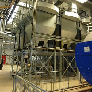
Dust discharge hoppers must be designed to prevent re-entrainment and allow for clean removal of particulate material. Compressed air must be dry and oil-free, and pulse manifolds should be mounted for easy access and replacement. Where space is constrained, compact horizontal designs can be used, but vertical designs offer improved dust drop-out and easier maintenance. In either case, the housing must be tailored to the specific process conditions — something Glosfume supports through its industry-specific filtration solutions.
Ceramic filtration provides high-efficiency particulate removal for hot gas processes, but its success depends on how well pressure drop is understood and managed. From filter layout to cleaning logic, every design decision plays a role in the long-term reliability of the system. Engineers and EPC contractors who design with pressure control in mind will deliver plants that run cleaner, longer, and more efficiently. With proper planning and the right ceramic elements, differential pressure becomes a design parameter — not a performance limitation.