



Industrial processes vary enormously in how they produce and handle exhaust gases. Whether in biomass combustion, animal by-product incineration, or metals recovery, no two gas streams are alike. Variables such as dust concentration, temperature profile, condensable gases, and spatial constraints influence how filtration must be approached. In this context, a pre-packaged system often falls short—underperforming on emissions or proving difficult to operate reliably.
Custom-engineered filtration systems bridge that gap. A properly tailored system captures particulate and gaseous pollutants with precision, integrates seamlessly into existing infrastructure, and maintains stable performance over years of operation. This article explores how filtration suppliers can take an installation from lab trial through to fully commissioned system, drawing on Glosfume’s step-by-step project methodology.
Step 1: Laboratory Testing and Sample Evaluation
Designing a suitable filter system starts with understanding the process emissions. The first step typically involves laboratory analysis of flue gas characteristics and particulate behaviour. Clients supply dust samples and, where possible, gas composition data under various load conditions. Tests are conducted to evaluate particle size distribution, moisture content, volatility, and reactivity with filtration media. For ceramic filters, these parameters determine surface loading rates, ash bonding risks, and pulse-cleaning effectiveness.
Glosfume uses this data to assess which ceramic element type—porosity, wall density, and geometry—offers the optimal balance between pressure drop and capture efficiency. Additionally, dry reagent interactions may be tested, particularly when acid gases or dioxins are present. Sodium bicarbonate, hydrated lime, and activated carbon are evaluated for reaction temperature and dosage compatibility.
Laboratory trials also help define cleaning cycle logic. For instance, if the dust cake proves tenacious, stronger pulse pressure or more frequent pulsing may be required. These insights help ensure the filter design is based on evidence—not assumption.
Step 2: On-Site Pilot Trials and Proof of Performance
Where lab data is insufficient, or where the gas stream is known to fluctuate, a field trial is often essential. A pilot system is installed on-site, either tapping into a slipstream or running in parallel with an existing unit. These scaled systems replicate the full mechanics of a ceramic filtration unit but with a reduced footprint and filter count.
During the trial, real-time data is collected on differential pressure, gas temperature, dust loading, and emissions performance. Cleaning logic is refined in live conditions, and reagent dosing is adjusted to reflect actual acid gas concentrations. This phase typically runs for several days to a few weeks, long enough to observe performance across operational cycles—start-up, steady load, and shutdown.
Pilot units are particularly helpful in sectors such as renewable biomass, where feedstock variability can introduce unpredictable ash behaviour. In one such case, a hospital biomass plant showed heavy potassium-based particulate emissions, which required a higher pulse frequency than standard systems. The trial allowed this to be addressed before final system design.
Step 3: Bespoke System Engineering and Layout Integration
Once performance is confirmed, a complete system is designed to match the site’s physical and operational parameters. This includes housing orientation, duct routing, hopper clearances, access doors, and element configuration. Filter media selection is finalised—whether for ultra-low PM2.5, high acid resistance, or consistent cleaning across multiple units.
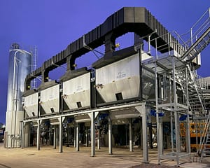
Glosfume’s bespoke filtration systems are engineered for modularity, meaning components such as pulse valves, access panels, and filter cassettes are arranged for easy maintenance without requiring confined space entry. Systems are designed to fit into difficult spaces—over rooftops, behind loading bays, or adjacent to thermal plant rooms.
For applications involving acid gases, the system includes reagent injection ports and dosing screw feeders. The filtration housing is thermally rated to handle direct flue gas entry without dilution air. Fan sizing and ductwork are selected to maintain flow within the optimum velocity band for cake development and cleaning recovery.
Step 4: Fabrication, Assembly, and Commissioning
All systems are built and tested at the manufacturer’s facility before delivery. This includes pressure testing, valve function checks, PLC programming, and touchscreen configuration. Once shipped to site, the system is either craned into place as a single module or assembled from prefabricated sections—minimising installation disruption.
Commissioning includes physical installation of ceramic elements, connection of compressed air, reagent lines, fan wiring, and control integration. Cleaning cycle parameters are fine-tuned using live pressure data. Safety interlocks and alarm conditions are validated. Most importantly, operators are trained in system behaviour, inspection routines, and fault diagnostics.
Some clients opt for remote access modules, allowing real-time monitoring and diagnostics from off-site locations. This is particularly useful in multi-plant networks or where maintenance staffing is limited.
Long-Term Adaptability and Lifecycle Support
Even after commissioning, a customised filtration system offers long-term adaptability. Element replacement intervals are predictable due to stable pressure drop trends, and reagent use remains efficient thanks to optimised dosing rates. Periodic service visits allow adjustment of cleaning logic and system upgrades as regulations evolve or throughput increases.
In a recent metal recovery plant, system airflow was increased by 30% after two years of successful operation. The modular design allowed the filter housing to be expanded without replacing the existing control panel or filter cassettes—demonstrating how forward-planned engineering adds long-term value.
Real-World Applications Across Industries
Sites that have benefitted from this approach include urban biomass plants where plume visibility was a concern, incinerators seeking DEFRA certification, and energy-from-waste systems with aggressive acid gases. In one EfW project, the client faced planning objections due to visible stack emissions. By running a pilot and refining the filtration logic, they achieved sub-2 mg/m³ PM10—securing approval and long-term operation.
Each installation draws on the same core process: understand the emission behaviour, validate the solution in practice, and deliver a tailored unit that performs over time without compromise.
Designing and delivering an effective industrial filtration system is never a plug-and-play exercise. It requires careful planning, rigorous testing, and ongoing support. By moving from trial to turnkey, site operators gain confidence that their emission control system is built to perform under real-world conditions—not just on paper. The result is reliable compliance, reduced operational risk, and long-term cost efficiency.